


R2-D2 has two PSIs. One is on the front of the dome and blinks red/blue. The other is on the back of the dome and blinks yellow/green. PSI stands for "Processor Status Indicator," which suggests it indicates what's going on inside R2's brain.
Yesterday, after a building rest during the winter, I put together some trial PSI displays. I'll probably go back and revise. Each display has several parts.
- Blinker board. Fiberopticproducts.com sells flasher boars, complete with LEDs specifically for this purpose; one flashes red long/blue short and one yellow long/green short (the company also sells various other blinker units. Each takes a 9-volt battery. Here is the link to the original item: http://www.fiberopticproducts.com/danise/cart.pl?db=stuff.dat&category=Dual. A flasher circuit can be made with transistors, resistors, capacitors and LEDs, but it's easy to use these pre-made pieces.
- Diffuser lens. Someone smart in the R2-D2 Builders Club suggested at least four years ago that the fluorescent light covers sold at Home Depot, Lowe's and the like look about right for R2's PSI light lens. The covers are inexpensive and sold by the sheet. I think they are made out of acrylic.
- Styrene. I made boxes out of white styrene to position the LEDs some distance away from the lens. I first tried a tube of white posterboard and then tried a tube of high-brightness printer paper. The styrene was sturdier and easier to work with.
I started with the rear PSI, thinking it would be better to make mistakes on that one first. Steps:
- I cut a piece of the fluorescent light cover to the height of the panel it was to go behind and made it wide enough to cover the circular opening.
- In the inner dome just behind the panel's position, I cut a rectangle wide enough to accept the assembly. This will be covered by the panel and doesn't need to be clean, though I'll probably sand the edges. (No one else might see how ugly it looks, but I'll know. ...)
- I attached the lens to the panel with painter's tape and silicone.
- I taped the box's walls together with packing tape and attached it to the panel with silicone.
- I cut a slit extending from a side to the center of the styrene box's rear wall, to accept the 9-volt battery wires.
- I taped the flasher board to the rear wall. (Again, tape, in this case regular Scotch tape. Nothing fancy.)
- I taped the rear wall/flasher board to the styrene box's walls (Scotch tape).
- And I put the box and panel through the inner dome. With the battery in place, it worked.
Video to come, once I get the video into my new computer.
Construction notes
- I set the blinker back in the hope of avoiding hot spots on the lens; I'd rather not people be able to immediately tell that the PSI is illuminated by two run-of-the-mill LEDs; let them think it's Star Warsy magic first. But I might do better by putting the lights closer.
- I made a styrene box because it was easy. But for bouncing the LEDs' photons around, a tube would be better.
- The fiberopticproducts.com circuits seem to be commonly used in the R2 group, but as with so many other parts of R2-D2, the PSI appearance is not uniform in each movie or scene. In the original movie, in fact, the red-to-blue change appears to be achieved by sliding a colored lens over a white light. In some shots, (this one, too) the front PSI appears to be half red and half blue (Is this because it is indeed half red and half blue, or because of the way a shadow falls across the PSI?). At some point, I might want to replicate this appearance.
Hobby comments
Once again, the differing incentives between hobbies and paid work lead to differing approaches in each sphere. The fun thing about hobbies is that one is allowed to wing it. For the PSI assemblies, there was no formal testing, no safety review board, no vendor bidding ... not even a drafted plan. Yet sometimes, especially in small companies, it's possible to move quickly in paid work. Last week, I set up a Facebook page for my company. It took minutes, and I populated fields according to what I thought would look good. Then I put it in front of other people at work, sought comment, and made some changes based on their feedback. Simple.
Photos
 Panel No. 14 (front PSI panel) and rectangle of fluorescent light lens
 Panel No. 14 (front PSI panel) and rectangle of fluorescent light lens, reverse
 Panel No. 14 (front PSI panel) and rectangle of fluorescent light lens, reverse
 Panel No. 14 (front PSI panel) and rectangle of fluorescent light lens, reverse
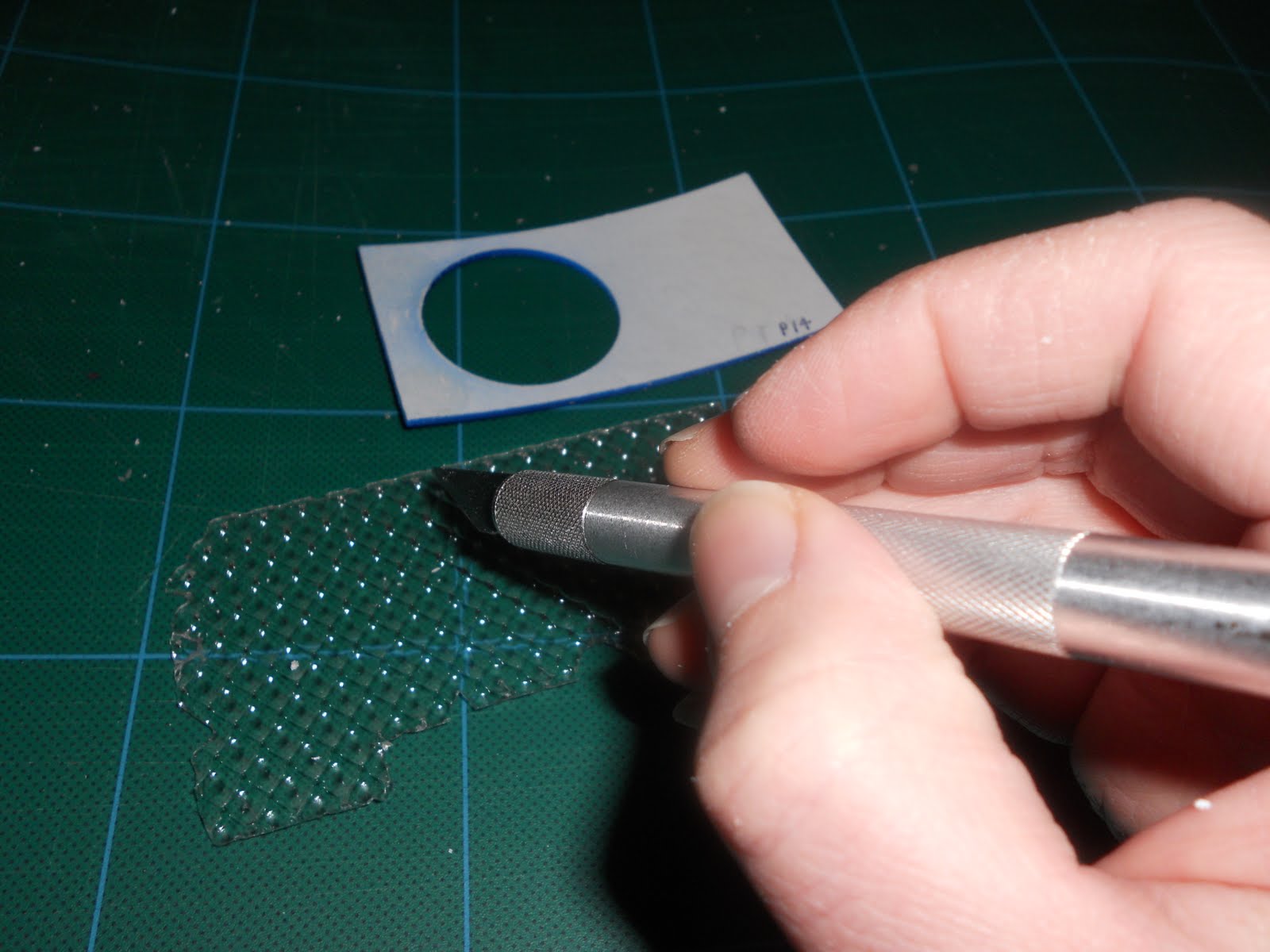 The lens sheet can be cut with a hobby knife or with scissors, but it is plastic and breaks into shards very easily. I found it worthwhile to score the plastic with the knife several times and then break it the rest of the way with my hands.
 The hole for the PSI needs to be large enough to accept the light housing and small enough to be hidden by the panel. This is the rear PSI cutout and will be filled by the yellow/green assembly. The hole is in the inner dome. It will be hidden, but I'll still probably sand it later. The holes above are for the dome buttons. I'll most likely use large round-head screws or bolts, filled in and painted blue, to fill them. Incidentally, these dome buttons are among the most mysterious of R2's parts. No one seems to know what they would be for if R2 were a real robot. Perhaps an ultrasonic detector?
  This is how the panel will fit into place and cover the hole for the housing. Another panel will fit around this panel. Again, this is for the rear PSI.
 This is how I attached the lens to the back PSI panel. It's nothing more than frog tape. On the front panel, I tried silicone, and that seemed to work well. The fluorescent lens can be bent to follow the panel's curve, but it needs to be held in place while it's drying, if silicone is used. (Model cement didn't work, possibly because the back of the lens, shown here facing up, is pointed, leaving little space on which the cement may adhere.)
 This is the front PSI panel (No. 14) and lens drying. Silicone has been used to attach them. The clamps are nothing more than dollar-store plastic clothespins, $1 per bag of five. They apply just enough pressure to do the job.
 This is what I tried first for the assembly. But it was hard to keep it in shape.
 Clear silicone from Walmart.
 I took a small piece of styrene, cut it lengthwise and cut notches to the right shape for the four walls of a box as tall as the PSI panel. Then I cut all the way through and taped the pieces together.


